
A Safe Way In Automation
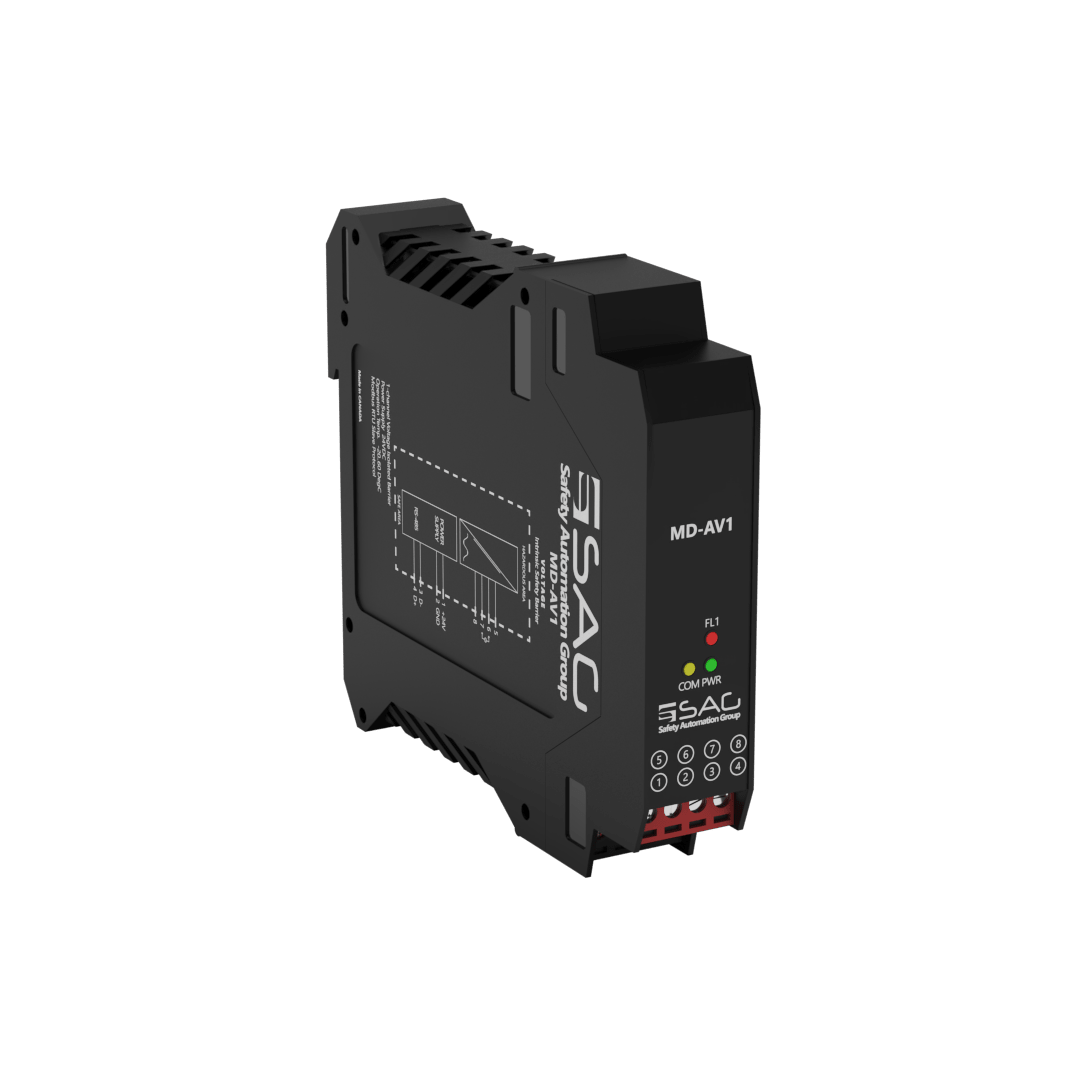
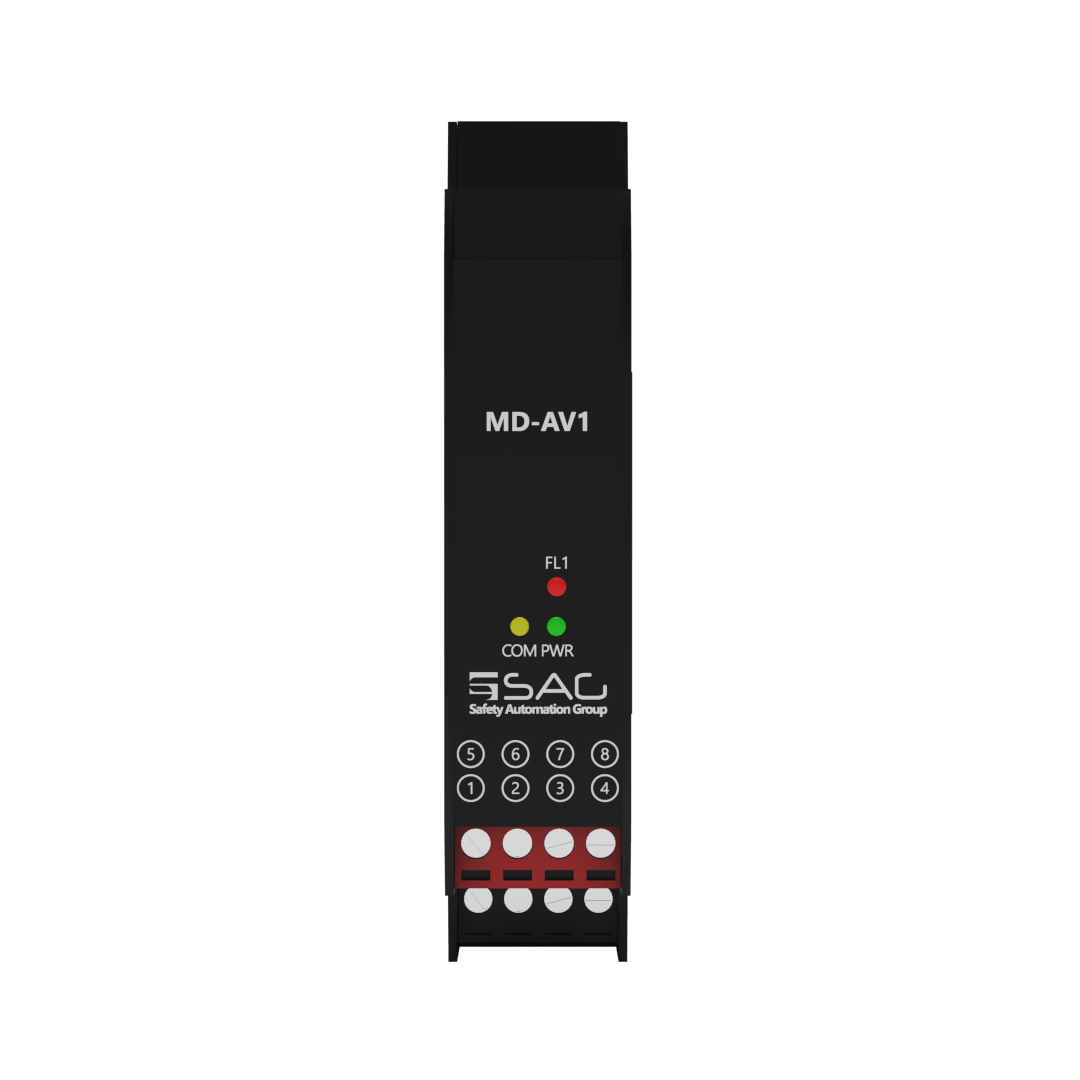
MD-AV1
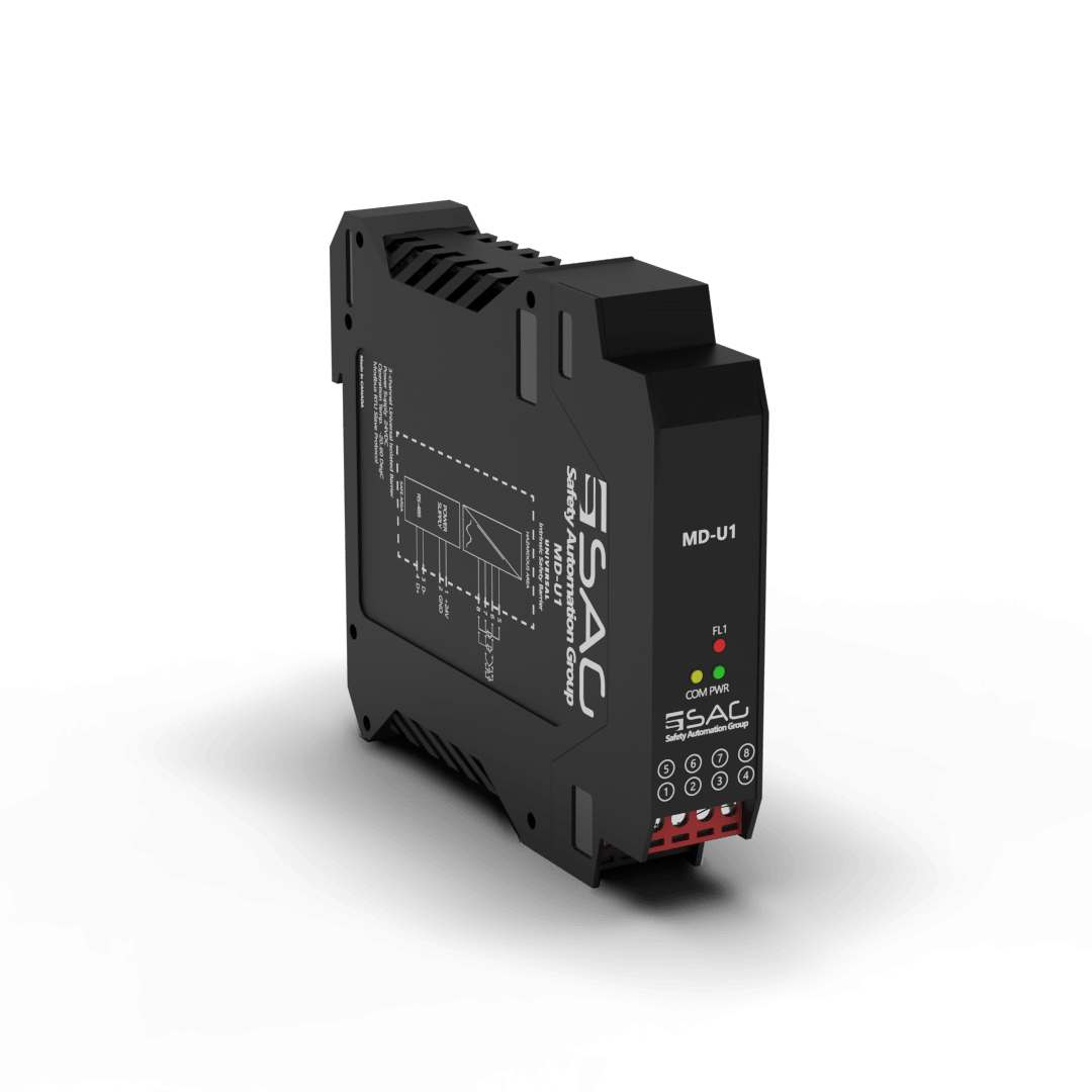
Voltage Sink Analog Intrinsic Safety Barrier (1-Channel)
The MD-AV1 is a 1-channel isolated barrier used for intrinsic safety applications. Each channel measures the voltage in a range of -5~5v, 0~5v, 0~10v, and -10~10v from the Hazardous area (Zone 0 or 1). It can be configured and transmitted with the MODBUS protocol RS-485 Interface on an integrated CPU, directly communicating with PLCs or PACs.
The MD-AV1 restricts the current and voltage level accordingly to prevent the risk of spark or ignition in a hazardous area. What’s more, the barrier is equipped with a fault LED to alert the user to short circuit and open circuit faults.
The current and power consumption of the input is about 208 mA and 5W, respectively. The power dissipation is less than 1W, and it is mounted on a 35 mm DIN mounting rail acc. Moreover, the environmental conditions are -20 to +60 °C and -25 to +65 °C as storage temperature.
Product Features
- Support 1 Channels
- 24 VDC Supply
- Analog Signal Type
- Modbus RTU
- RS-485 Interface
- Connection with Screw Terminals
- Configurable with Modbus Protocol
- Voltage Input


Technical Specifications
| GENERAL SPECIFICATION | |
| Signal Type | Analog Input |
| Number of Channels | 1 Channel |
| SUPPLY | |
| Rated Voltage | 24 VDC Nom (20-30 VDC) Reverse Polarity Protected |
| Connection | Terminal 1 PIN 1(+24 VDC), Terminal 1 PIN 2 (GND) |
| Power Dissipation | < 1 W |
| Current Consumption | Approx. 208mA |
| Max. Power Consumption | 5 W |
| INPUT | |
| Input | Voltage |
| Connection | Terminals 2 |
| Rated Values | - |
| Integration Time | 400 ms |
| Input Range | (sink, -10 to 10 volts) |
| VOLTAGE | |
| Range | 0 ... 10 V, 2 ... 10 V, 0 ... 1 V, -100 ... 100 mV, -10 … 10V |
| Resolution | - |
| DEVIATION | |
| Voltage | 0.1 % of Span |
| DATA CONNECTION | |
| Modbus RTU | RS-485 connection up to 115.2 kbps for Monitor/ Configuration |
| Connection | Terminal 3 (), Terminal 4 () |
| ISOLATION | |
| Input / Power Supply | 1500 VDC Example. safe electrical isolation by reinforced insulation according to IEC/EN 61010^-1 Rated insulation voltage 300 Veff test voltage 3 kV, 50 Hz, 1 min. |
| ENVIRONMENTAL CONDITIONS | |
| Operation Temperature | Temperature Limits –20 to +60 °C |
| Storage Temperature | Temperature Limits –25 to +65 °C |
| MOUNTING | |
| Mounting | On 35 mm DIN Mounting Rail Acc. to EN 60715:2001 |
| APPROVALS | |
| IEC60079-0, IEC60079-11, IEC60079-15 | |
| FM & FM-C No.3024643,3029921C,conforms to Class 3600,3610,3611,3810 | |
| LOCATION | |
| Safe Area/Non-Hazardous Locations or Zone 2, Group IIC T4, Class I, Division 2, Groups A, B, C, D Temperature Code T4 and Class I, Zone 2, Group IIC, IIB, IIA T4 installation | |
| SAFETY DESCRIPTION | |
| ATEX | II 1 G Ex ic [ia Ga] IIC T4 Gc, II 3 G Ex ic [ic] IIC T4 Gc, II 1 D Ex ic [ia IIIC Da] IIC Gc II 3 D Ex ic [ic IIIC Dc] IIC Gc |
| IECEx | Ex ic [ia Ga] IIC T4 Gc, Ex ic [ic] IIC T4 Gc, Ex ic [ia IIIC Da] IIC Gc, Ex ic [ic IIIC Dc] IIC Gc |
| FM | Class 1, Zone 2 AEx ic [ia Ga] IIC T4 Gc, Class I, Zone 2 AEx [ic] IIC T4 Gc Zone 20 Ex ic [ia IIIC Da] IIC Gc, Zone 2 Ex ic [ic IIIC Dc] IIC Gc |
| North American Zones | Class I, Division 2, Groups A, B, C, D T4, Class II, Division 2, Groups F, G |
| ASSOCIATED ELECTRICAL APPARATUS | |
| Vo/Voc | 17.0 V, Io/Isc = 85 mA, Po/Po = 1.45 W |
| IECEx | 24V, Ci = 6 nF, Li = 0 nH. Um = 30 V, -20 °C ≤ Ta ≤ 60°C. |
Support & Download