A Safe Way In Automation
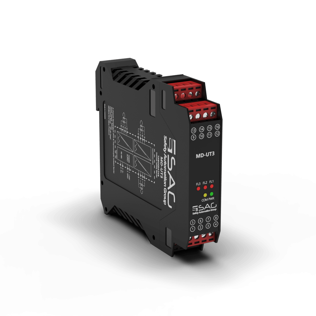
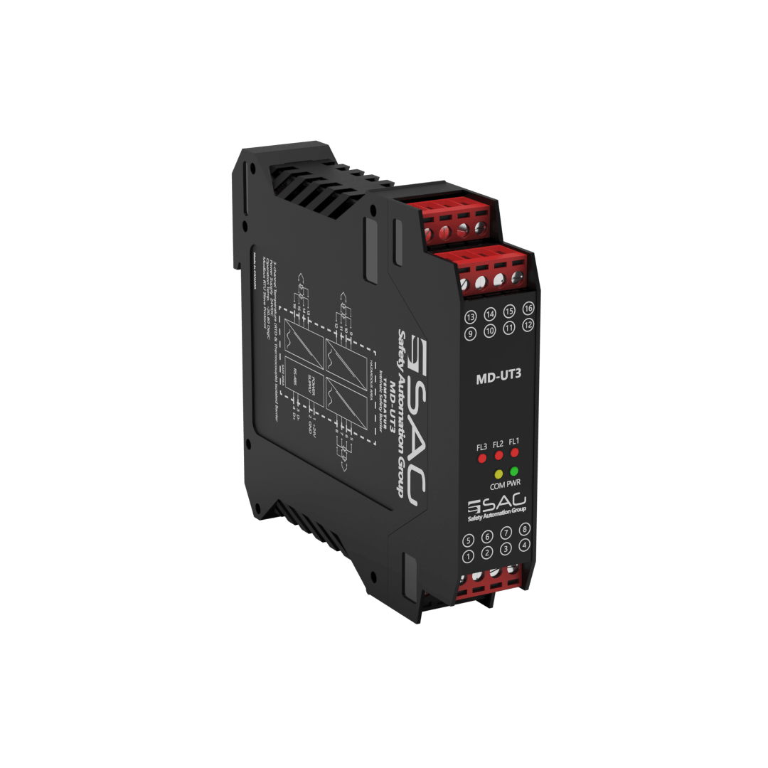
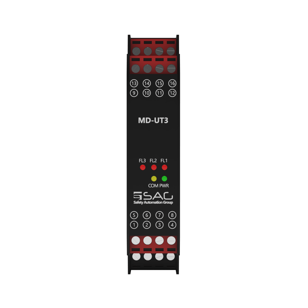
MD-UT3
Universal Temperature Intrinsic Safety Barrier (3-Channel)
The MD-UT is a universal temperature intrinsically safe barrier. It can measure analog signals and be configured with the Modbus protocol. It can be purchased with 1-2 or 3 channels. The current and power consumption of the input is about 208 mA and 5W respectively, and the power dissipation is less than 1W with a 35 mm DIN mounting rail acc.
The MD-UT3 is a 3-Channel Isolated Barrier that can measure temperature and support various temperature sensors, including 2-3 and 4 wire RTDs, from PT10 to PT1000. When accuracy is not critical you can use 2-wire RTDs. Of course, 3 and 4-wire constructions are used in industries and laboratories where close accuracy is imperative. In addition to this, the thermocouple sensors can be read with different types (B, E, J, K, L, R, N, S, T-Type). The CJC is internal, and its deviation is about ±0.8 K.
When installed in hazardous areas, the temperature value collected is transmitted back to the safe areas through the Modbus protocol. Also, the environmental conditions are -20 to +60 °C as an operation and -25 to +65 °C as storage temperature.
Product Features
- Support 3 Channels
- 24 VDC Supply
- Analog Signal Type
- Modbus RTU
- RS-485 Interface
- Connection with Screw Terminals
- RTD
- Thermocouple
- Configurable with Modbus Protocol


Technical Specifications
GENERAL SPECIFICATION | |
| Signal Type | Analog Input |
| Number of Channels | 3 Channel |
SUPPLY | |
| Rated Voltage | 24 VDC Nom (20-30 VDC) Reverse Polarity Protected |
| Connection | Terminal 1 PIN 1(+24 VDC), Terminal 1 PIN 2 (GND) |
| Power Dissipation | < 1 W |
| Current Consumption | Approx. 208mA |
| Max. Power Consumption | 5 W |
INPUT | |
| Input | Thermocouple, 2-3-4 Wire RTD |
| Connection | Terminals 2,3,4 |
| Rated Values | - |
| Integration Time | 400 ms |
| Input Range | ±500 mV (TC/mV), 0-4 kΩ (RTD/res), (sink, -10 to 10 volts), (sink 0-20mA) |
RTD | |
| RTD | (PT10,PT50,PT100,PT500,PT1000) |
| Type of Measuring | 2,3 and 4 Wire |
| Measurement Loop Monitoring | Sensor Breakage |
| Measuring RTD Current | 323 μA |
THERMOCOUPLE | |
| Thermocouple | B, E, J, K, L, N, R, S, T – Type (IEC 584-1: 1995) |
| Cold Junction Compensation | Internal |
| Measurement Loop Monitoring | - |
DEVIATION | |
| RTD | Max 0.1% of Span |
| Thermocouple | Deviation of CJC: ±0.8 K |
DATA CONNECTION | |
| Modbus RTU | RS-485 connection up to 115.2 kbps for Monitor/ Configuration |
| Connection | Terminal1 PIN 3 (D-), Terminal1 PIN 4 (D+) |
ISOLATION | |
| Input / Power Supply | 1500 VDC Example. safe electrical isolation by reinforced insulation according to IEC/EN 61010^-1 Rated insulation voltage 300 Veff test voltage 3 kV, 50 Hz, 1 min. |
ENVIRONMENTAL CONDITIONS | |
| Operation Temperature | Temperature Limits –20 to +60 °C |
| Storage Temperature | Temperature Limits –25 to +65 °C |
| MOUTING | |
| Mounting | On 35 mm DIN Mounting Rail Acc. to EN 60715:2001 |
APPROVALS | |
| IEC60079-0, IEC60079-11, IEC60079-15 | |
| FM & FM-C No.3024643,3029921C,conforms to Class 3600,3610,3611,3810 | |
LOCATION | |
| Safe Area/Non Hazardous Locations or Zone 2, Group IIC T4, Class I, Division 2, Groups A, B, C, D Temperature Code T4 and Class I, Zone 2, Group IIC, IIB, IIA T4 installation | |
SAFETY DESCRIPTION | |
| ATEX | II 1 G Ex ic [ia Ga] IIC T4 Gc, II 3 G Ex ic [ic] IIC T4 Gc, II 1 D Ex ic [ia IIIC Da] IIC Gc II 3 D Ex ic [ic IIIC Dc] IIC Gc |
| IECEx | Ex ic [ia Ga] IIC T4 Gc, Ex ic [ic] IIC T4 Gc, Ex ic [ia IIIC Da] IIC Gc, Ex ic [ic IIIC Dc] IIC Gc |
| FM | Class 1, Zone 2 AEx ic [ia Ga] IIC T4 Gc, Class I, Zone 2 AEx [ic] IIC T4 Gc Zone 20 Ex ic [ia IIIC Da] IIC Gc, Zone 2 Ex ic [ic IIIC Dc] IIC Gc |
| North American Zones | Class I, Division 2, Groups A, B, C, D T4, Class II, Division 2, Groups F, G |
ASSOCIATED ELECTRICAL APPARATUS | |
| Vo/Voc | 17.0 V, Io/Isc = 85 mA, Po/Po = 1.45 W |
| IECEx | 24V, Ci = 6 nF, Li = 0 nH. Um = 30 V, -20 °C ≤ Ta ≤ 60°C. |
Support & Download