A Safe Way In Automation
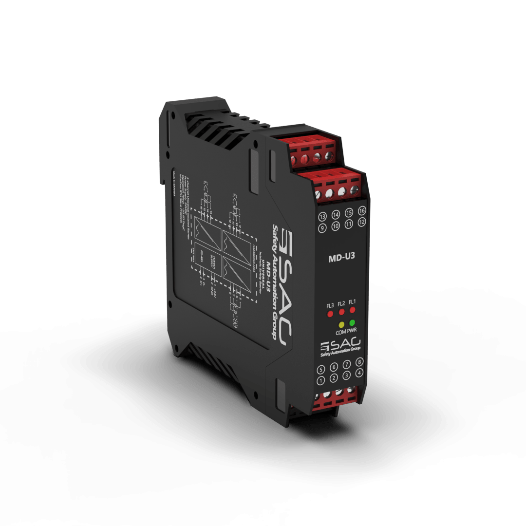
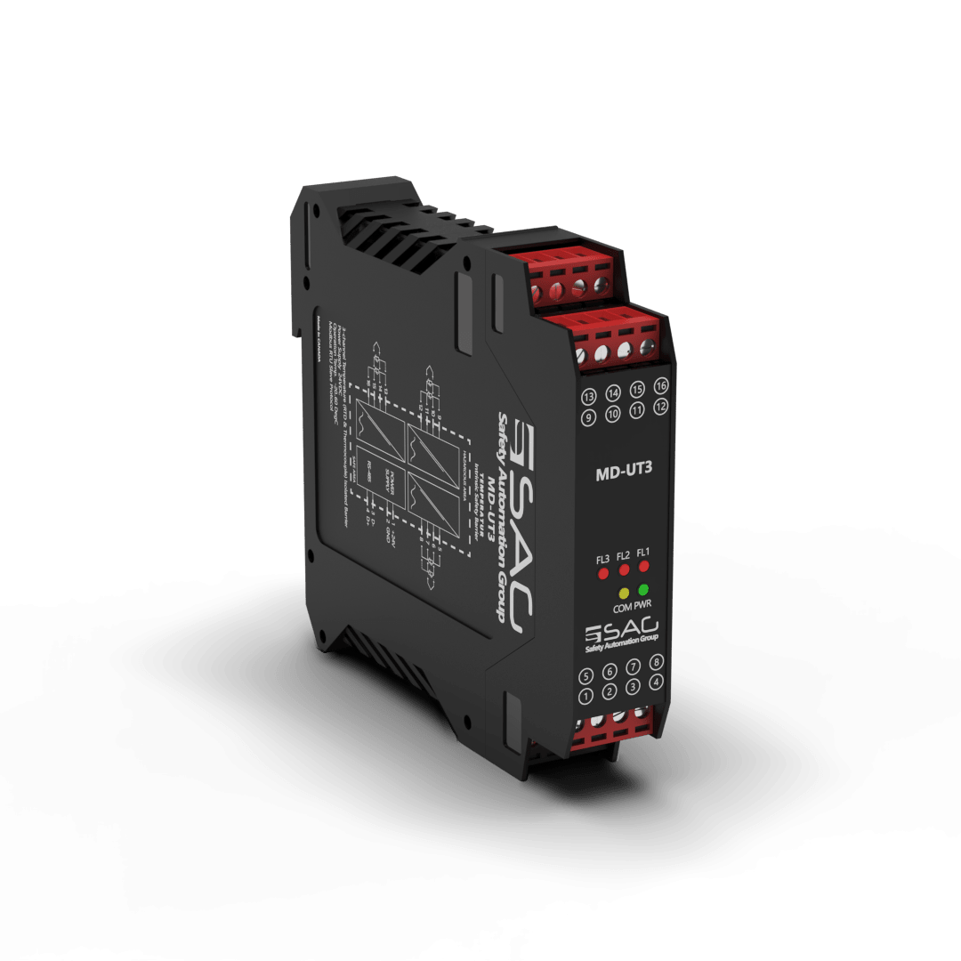
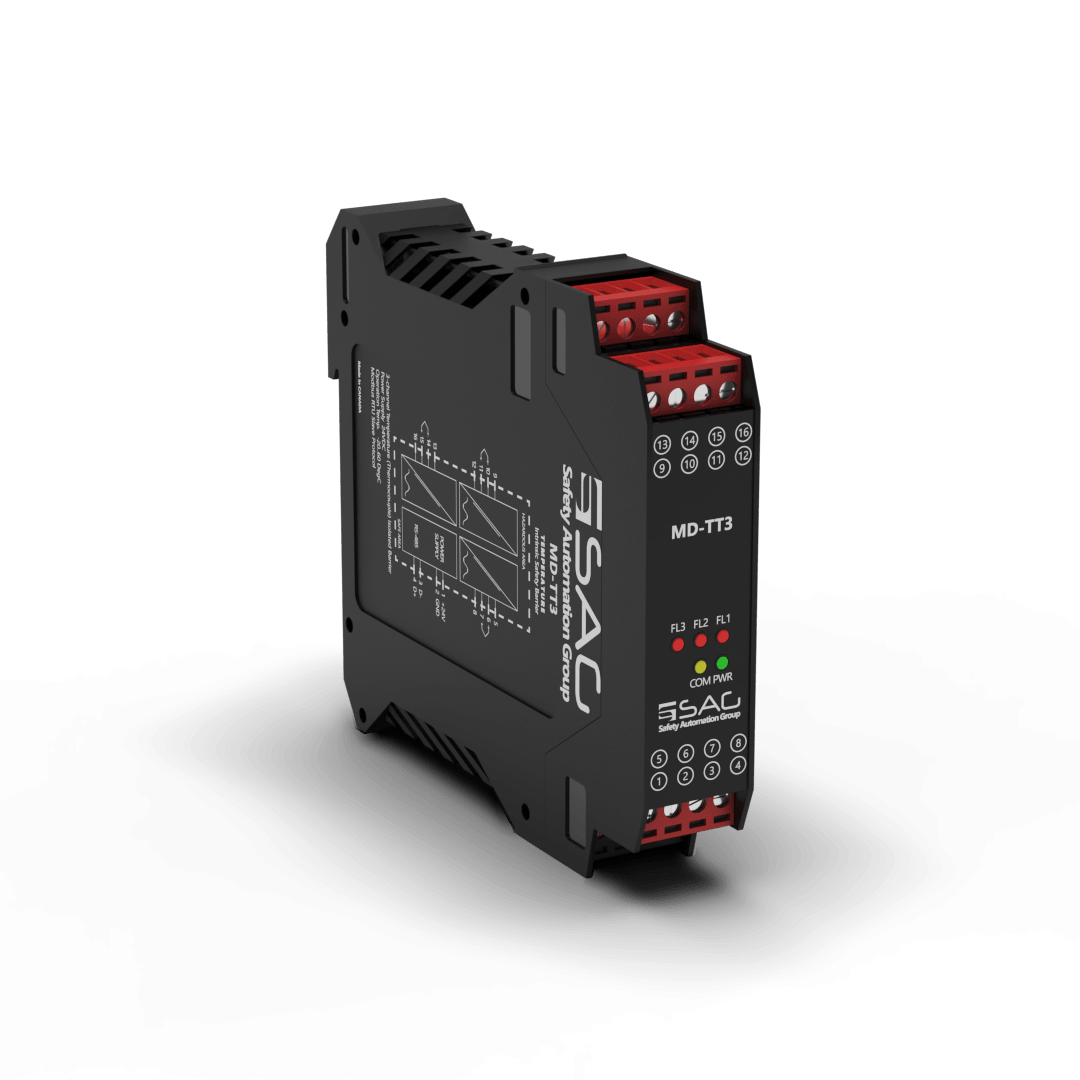
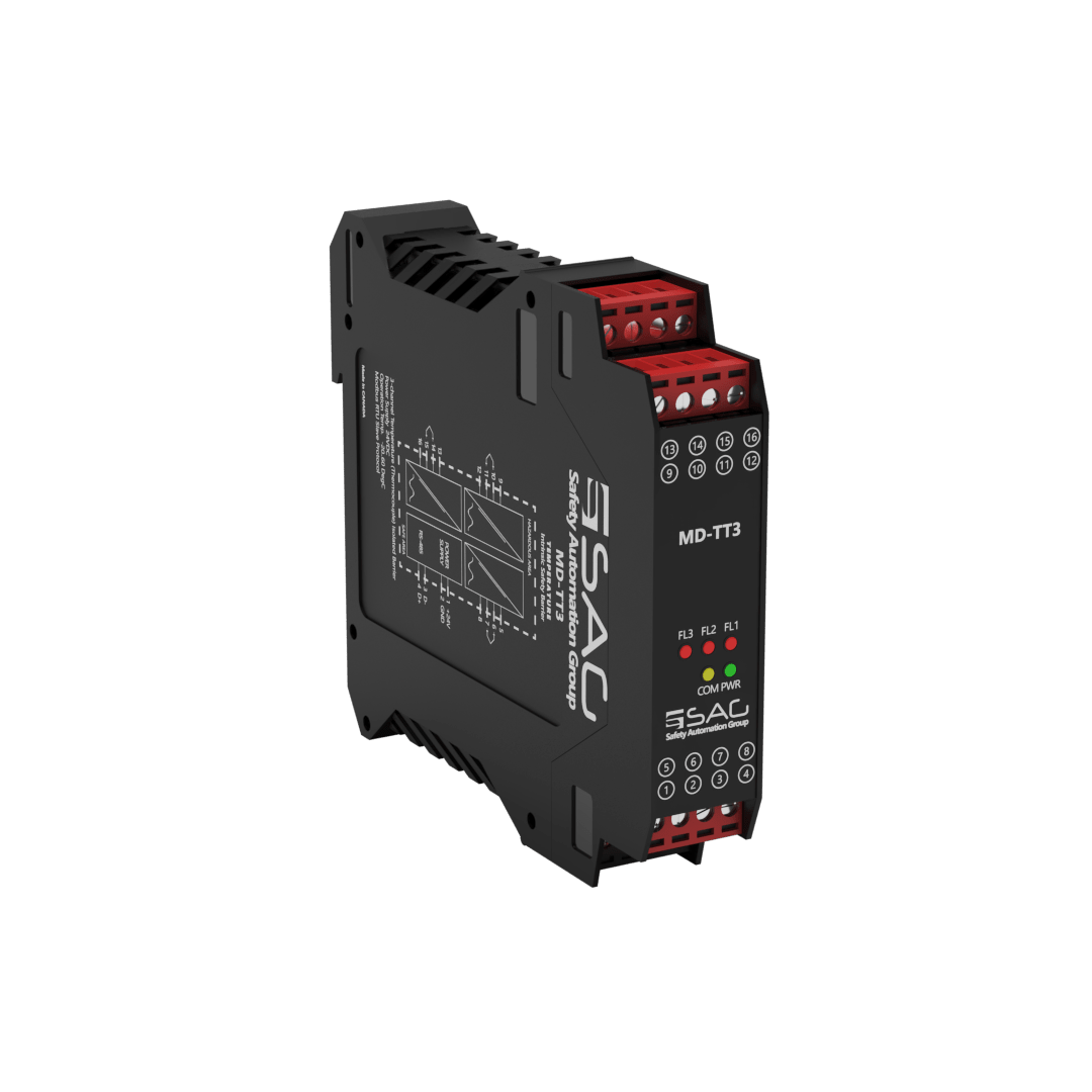
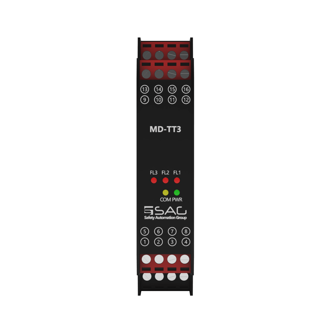
MD-TT3
Thermocouple Temperature Intrinsic Safety Barrier (3-Channel)
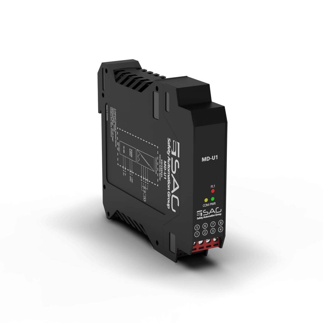
The MD-TT is an isolated barrier that prevents the risk of excess temperature, arcs, and sparks igniting the explosive atmosphere present in a hazardous area. It features up to three channels, and every single of them supports analog signals and can be configured with the MODBUS protocol.
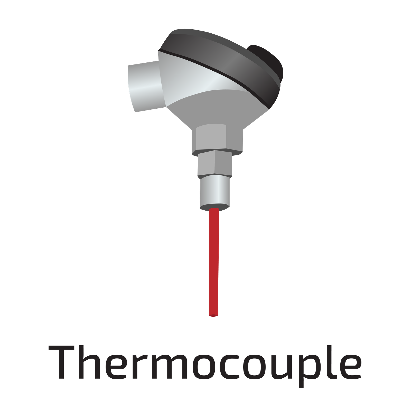
The MD-TT is a 3-channel isolated barrier that can measure temperature from a thermocouple. It supports a wide range of sensors including B, E, J, K, N, R, S, and T sensor types with an internal cold junction. The temperature value transmits to a safe area through the MODBUS protocol for processing and monitoring purposes, which is done via an integrated CPU platform.
Moreover, the MD-TT consumes current and power up to 208 mA and 5W respectively. Its power dissipation is acceptably less than 1W. And the environmental conditions are -20 to +60 °C as an operation and -25 to +65 °C as storage temperature.
Product Features
- Support 3 Channels
- 24 VDC Supply
- Analog Signal Type
- Modbus RTU
- RS-485 Interface
- Connection with Screw Terminals
- Configurable with Modbus Protocol
- Measuring Temperature from Thermocouples


Technical Specifications
| GENERAL SPECIFICATION | |
| Signal Type | Analog Input |
| Number of Channels | 3 Channel |
| SUPPLY | |
| Rated Voltage | 24 VDC Nom (20-30 VDC) Reverse Polarity Protected |
| Connection | Terminal 1 PIN 1(+24 VDC), Terminal 1 PIN 2 (GND) |
| Power Dissipation | < 1 W |
| Current Consumption | Approx. 208mA |
| Max. Power Consumption | 5 W |
| INPUT | |
| Input | Thermocouple |
| Connection | Terminals 2,3,4 |
| Rated Values | - |
| Integration Time | 400 ms |
| Input Range | ±500 mV (TC/mV) |
| THERMOCOUPLE | |
| Thermocouple | B, E, J, K, L, N, R, S, T – Type (IEC 584-1: 1995) |
| Cold Junction Compensation | Internal |
| Measurement Loop Monitoring | - |
| DEVIATION | |
| Thermocouple | Deviation of CJC: ±0.8 K |
| DATA CONNECTION | |
| Modbus RTU | RS-485 connection up to 115.2 kbps for Monitor/ Configuration |
| Connection | Terminal1 PIN 3 (D-), Terminal1 PIN 4 (D+) |
| ISOLATION | |
| Input / Power Supply | 1500 VDC Example. safe electrical isolation by reinforced insulation according to IEC/EN 61010^-1 Rated insulation voltage 300 Veff test voltage 3 kV, 50 Hz, 1 min. |
| ENVIRONMENTAL CONDITIONS | |
| Operation Temperature | Temperature Limits –20 to +60 °C |
| Storage Temperature | Temperature Limits –25 to +65 °C |
| MOUNTING | |
| Mounting | On 35 mm DIN Mounting Rail Acc. to EN 60715:2001 |
| APPROVALS | |
| IEC60079-0, IEC60079-11, IEC60079-15 | |
| FM & FM-C No.3024643,3029921C,conforms to Class 3600,3610,3611,3810 | |
| LOCATION | |
| Safe Area/Non-Hazardous Locations or Zone 2, Group IIC T4, Class I, Division 2, Groups A, B, C, D Temperature Code T4 and Class I, Zone 2, Group IIC, IIB, IIA T4 installation | |
| SAFETY DESCRIPTION | |
| ATEX | II 1 G Ex ic [ia Ga] IIC T4 Gc, II 3 G Ex ic [ic] IIC T4 Gc, II 1 D Ex ic [ia IIIC Da] IIC Gc II 3 D Ex ic [ic IIIC Dc] IIC Gc |
| IECEx | Ex ic [ia Ga] IIC T4 Gc, Ex ic [ic] IIC T4 Gc, Ex ic [ia IIIC Da] IIC Gc, Ex ic [ic IIIC Dc] IIC Gc |
| FM | Class 1, Zone 2 AEx ic [ia Ga] IIC T4 Gc, Class I, Zone 2 AEx [ic] IIC T4 Gc Zone 20 Ex ic [ia IIIC Da] IIC Gc, Zone 2 Ex ic [ic IIIC Dc] IIC Gc |
| North American Zones | Class I, Division 2, Groups A, B, C, D T4, Class II, Division 2, Groups F, G |
| ASSOCIATED ELECTRICAL APPARATUS | |
| Vo/Voc | 17.0 V, Io/Isc = 85 mA, Po/Po = 1.45 W |
| IECEx | 24V, Ci = 6 nF, Li = 0 nH. Um = 30 V, -20 °C ≤ Ta ≤ 60°C. |
Support & Download