A Safe Way In Automation
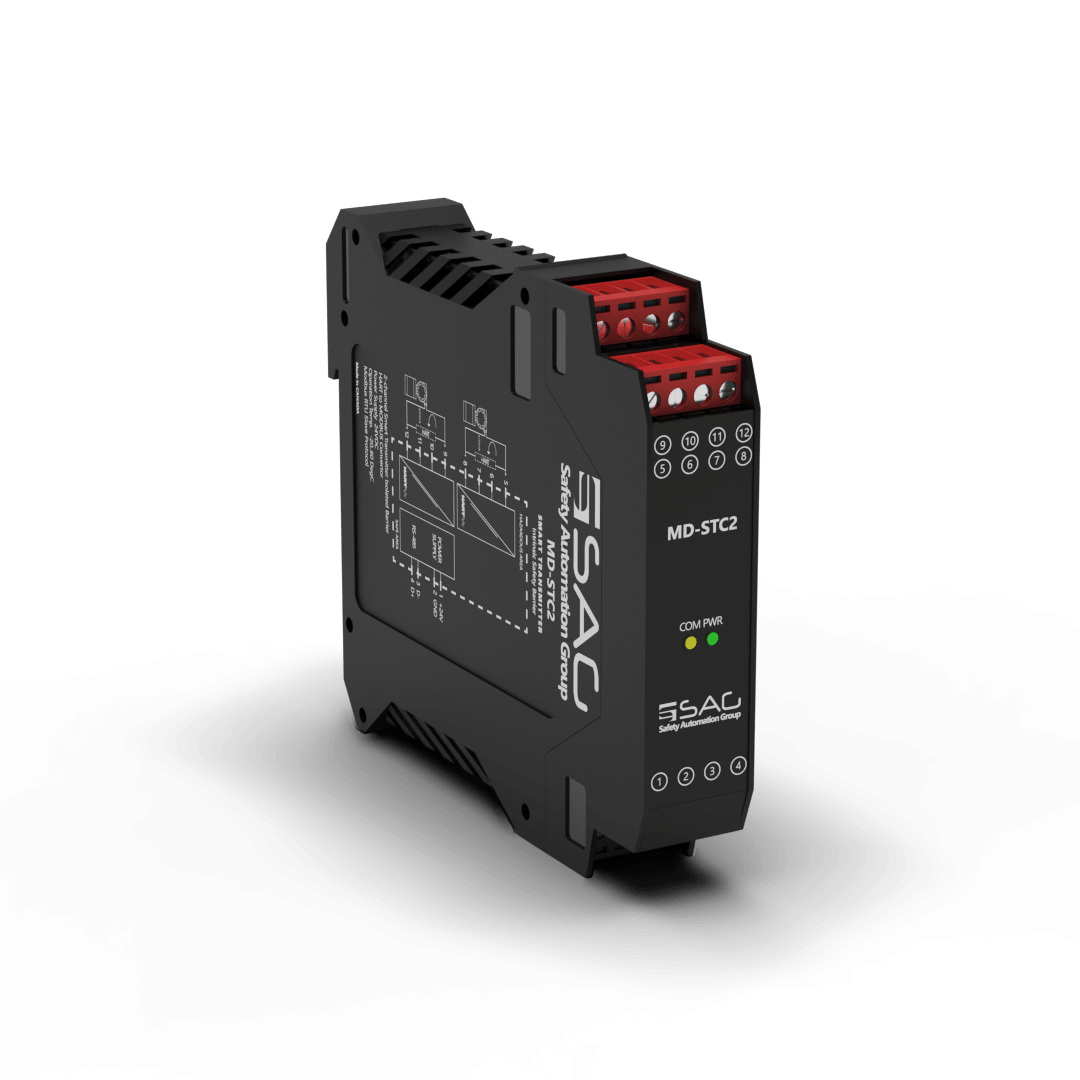
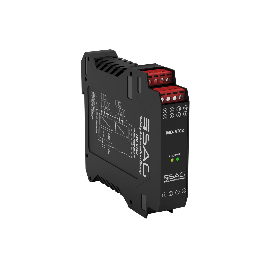
MD-STC2
Modbus Smart Transmitter Intrinsic Safety Barrier(2-Channel)
The MD-STC2 is 2-Channel smart transmitter isolated barrier used to read 2-wire smart transmitters in hazardous areas with support two channels. Using the MODBUS Protocol, data is collected from a hazardous area with 4 ~ 20 mA analog current signal (Zone 0 or Zone 1). The data is then safely transmitted back to the safe area, with a bit rate up to 115.2 kbps via the RS-485 interface, making it ideal for convenient, remote monitoring from a safe area. Note: Using this protocol, data is only transferred from the hazardous area to the safe area, with no more analog signals reproduced in the safe area.
The input of the MD-STC consumes 208 mA current and 5W, with a power dissipation of less than 1W, and a 24 VDC nominal with reversed polarity protected power. As an operation, the environmental conditions are -20 to +60 °C as an operation and -25 to +65 °C as storage temperature. The MD-STC has a sturdy 35 mm DIN mounting rail acc.
Product Features
- Support 2 Channels
- 24 VDC Supply
- Analog Signal Type
- Modbus RTU
- RS-485 Interface
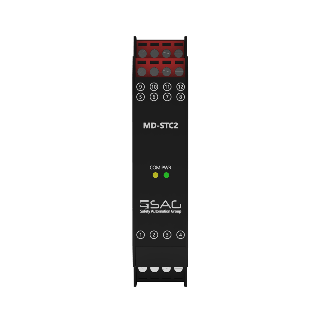
- Connection with Screw Terminals
- 2 Wire Smart Transmitters
- Configurable with Modbus Protocol
- 4-20 mA Passive Input


Technical Specifications
| GENERAL SPECIFICATION | |
| Signal Type | Analog Input |
| Number of Channels | 2 Channel |
| SUPPLY | |
| Rated Voltage | 24 VDC Nom (20-30 VDC) Reverse Polarity Protected |
| Connection | Terminal 1 PIN 1(+24 VDC), Terminal 1 PIN 2 (GND) |
| Power Dissipation | < 1 W |
| Current Consumption | Approx. 208mA |
| Max. Power Consumption | 5 W |
| INPUT | |
| Input | 4...20 mA |
| Connection | Terminals 3,4 |
| Connection Side | Field Side |
| Available Voltage | 400 ms> 16 V at 20 mA |
| OUTPUT | |
| Output | Modbus over RS-485 |
| Connection | Terminals 1 |
| Connection Side | Control Side |
| GALVANIC ISOLATION | |
| Input / Power Supply | 1500 VDC Example. safe electrical isolation by reinforced insulation according to IEC/EN 61010^-1 Rated insulation voltage 300 Veff test voltage 3 kV, 50 Hz, 1 min. |
| Output/ Power Supply | Functional Insulation, Rated Insulation Voltage 50 V AC |
| Output/ Output | Functional Insulation, Rated Insulation Voltage 50 V AC |
| TRANSFER CHARACTERISTICS | |
| Deviation | At –20 to +60 °C, 4...20 mA : ≤10 μA incl. |
| Influence of Ambient Temperature | 0.25 μA/K |
| DATA CONNECTION | |
| Modbus RTU | RS-485 connection up to 115.2 kbps for Monitor/ Configuration |
| Connection | Terminal1 PIN 3 (D-), Terminal1 PIN 4 (D+) |
| MOUNTING | |
| Mounting | On 35 mm DIN Mounting Rail Acc. to EN 60715:2001 |
| ENVIRONMENTAL CONDITIONS | |
| Operation Temperature | Temperature Limits –20 to +60 °C |
| Storage Temperature | Temperature Limits –25 to +65 °C |
| APPROVALS | |
| IEC60079-0, IEC60079-11, IEC60079-15 | |
| FM & FM-C No.3024643,3029921C,conforms to Class 3600,3610,3611,3810 | |
| LOCATION | |
| Safe Area/Non-Hazardous Locations or Zone 2, Group IIC T4, Class I, Division 2, Groups A, B, C, D Temperature Code T4 and Class I, Zone 2, Group IIC, IIB, IIA T4 installation | |
| SAFETY DESCRIPTION | |
| ATEX | II 1 G Ex ic [ia Ga] IIC T4 Gc, II 3 G Ex ic [ic] IIC T4 Gc, II 1 D Ex ic [ia IIIC Da] IIC Gc II 3 D Ex ic [ic IIIC Dc] IIC Gc |
| IECEx | Ex ic [ia Ga] IIC T4 Gc, Ex ic [ic] IIC T4 Gc, Ex ic [ia IIIC Da] IIC Gc, Ex ic [ic IIIC Dc] IIC Gc |
| North American Zones | Class 1, Zone 2 AEx ic [ia Ga] IIC T4 Gc, Class I, Zone 2 AEx [ic] IIC T4 Gc Zone 20 Ex ic [ia IIIC Da] IIC Gc, Zone 2 Ex ic [ic IIIC Dc] IIC Gc |
| North American Div | Class I, Division 2, Groups A, B, C, D T4, Class II, Division 2, Groups F, G |
| ASSOCIATED ELECTRICAL APPARATUS | |
| Vo/Voc | 17.0 V, Io/Isc = 85 mA, Po/Po = 1.45 W |
| IECEx | 24V, Ci = 6 nF, Li = 0 nH. Um = 30 V, -20 °C ≤ Ta ≤ 60°C. |
Support & Download