A Safe Way In Automation
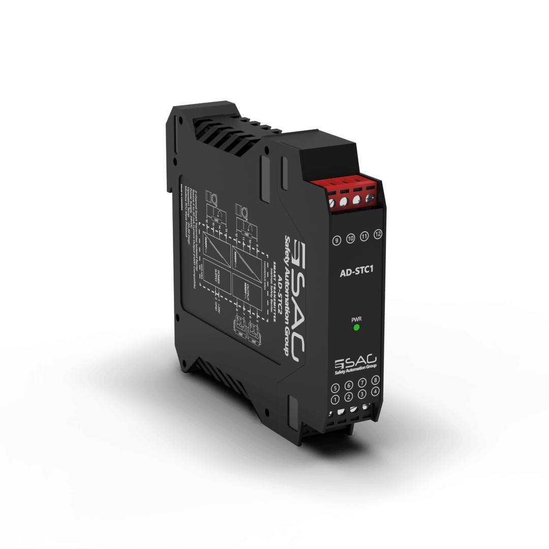
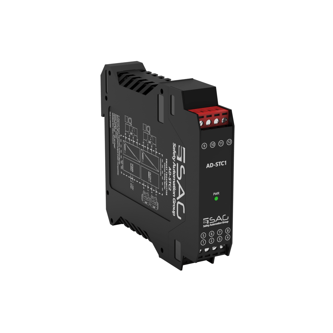
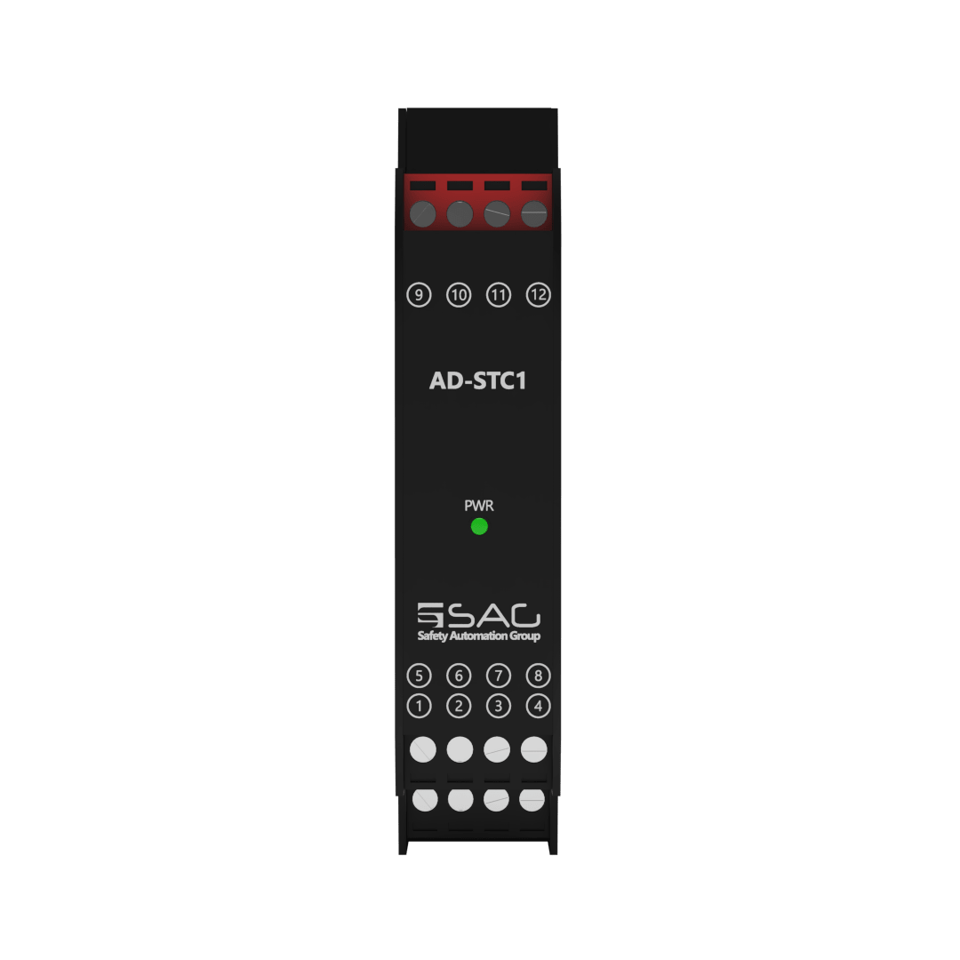
AD-STC1
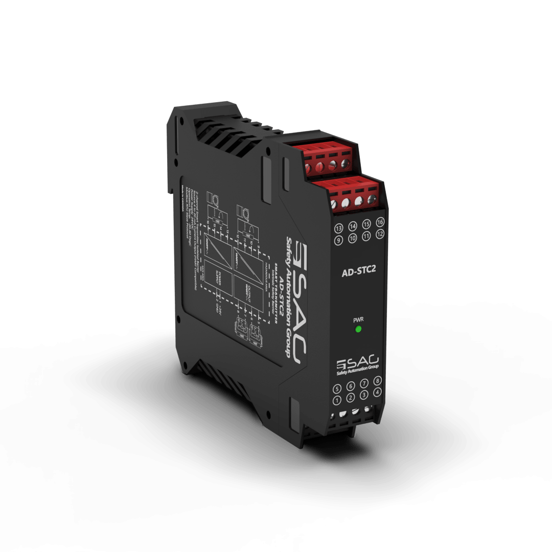
HART Smart Transmitter Intrinsic Safety Barrier(1-Channel)
The AD-STC is an intrinsically safe barrier, designed with 1 or 2 channel(s) for reading 2-wire smart transmitters in hazardous areas. It reads data from hazardous areas through a 4 ~ 20 mA analog current signal via the HART protocol, which it then transfers to the safe area. After that, the collected data at the safe area is transmitted to the station, through a reproduced analog signal similar to the one in the hazardous area.
Moreover, digital signals may be superimposed on the input signal in the hazardous or safe area, which it then transfers bi-directionally. The current and power consumption of the input is about 208 mA and 5W, respectively, and the power dissipation is less than 1W. The environmental conditions are -20 to +60 °C as an operation and -25 to +65 °C as storage temperature. The AD-STC is mounted on a sturdy 35 mm DIN mounting rail acc.
Product Features
- Support 1 Channel
- 24 VDC Supply
- Connection with Screw Terminals
- 2 Wire Smart Transmitters
- 4-20 mA Passive Input Source Output


Technical Specifications
| GENERAL SPECIFICATION | |
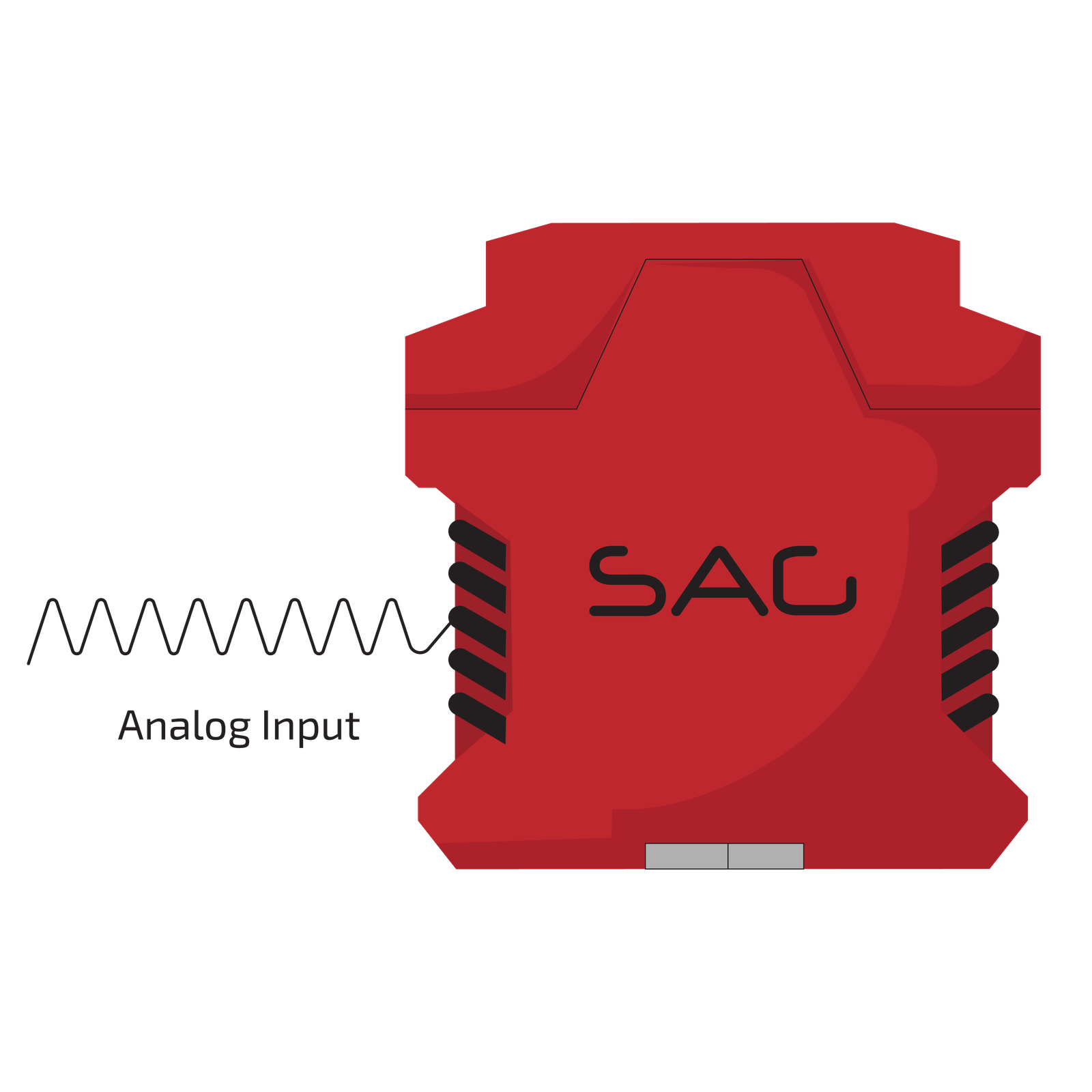
| Signal Type | Analog Input |
| Number of Channels | 1 Channel |
| SUPPLY | |
| Rated Voltage | 24 VDC Nom (20-30 VDC) Reverse Polarity Protected |
| Connection | Terminal 1 PIN 1(+24 VDC), Terminal 1 PIN 2 (GND) |
| Power Dissipation | < 1 W |
| Current Consumption | Approx. 208mA |
| Max. Power Consumption | 5 W |
| INPUT | |
| Input | 4...20 mA |
| Connection | Terminals 3 |
| Connection Side | Field Side |
| Available Voltage | 400 ms> 16 V at 20 mA |
| OUTPUT | |
| Output | 4...20 mA |
| Connection | Terminals 2 |
| Connection Side | Control Side |
| Load | 0...550 Ω at 20 mA |
| Ripple | max. 50 μA rms |
| GALVANIC ISOLATION | |
| Input / Power Supply | 1500 VDC Example. safe electrical isolation by reinforced insulation according to IEC/EN 61010^-1 Rated insulation voltage 300 Veff test voltage 3 kV, 50 Hz, 1 min. |
| Output/ Power Supply | Functional Insulation, Rated Insulation Voltage 50 V AC |
| Output/ Output | Functional Insulation, Rated Insulation Voltage 50 V AC |
| TRANSFER CHARACTERISTICS | |
| Deviation | At –20 to +60 °C, 4...20 mA : ≤10 μA incl. |
| Influence of Ambient Temperature | 0.25 μA/K |
| MOUNTING | |
| Mounting | On 35 mm DIN Mounting Rail Acc. to EN 60715:2001 |
| ENVIRONMENTAL CONDITIONS | |
| Operation Temperature | Temperature Limits –20 to +60 °C |
| Storage Temperature | Temperature Limits –25 to +65 °C |
| APPROVALS | |
| IEC60079-0, IEC60079-11, IEC60079-15 | |
| FM & FM-C No.3024643,3029921C,conforms to Class 3600,3610,3611,3810 | |
| LOCATION | |
| Safe Area/Non-Hazardous Locations or Zone 2, Group IIC T4, Class I, Division 2, Groups A, B, C, D Temperature Code T4 and Class I, Zone 2, Group IIC, IIB, IIA T4 installation | |
| SAFETY DESCRIPTION | |
| ATEX | II 1 G Ex ic [ia Ga] IIC T4 Gc, II 3 G Ex ic [ic] IIC T4 Gc, II 1 D Ex ic [ia IIIC Da] IIC Gc II 3 D Ex ic [ic IIIC Dc] IIC Gc |
| IECEx | Ex ic [ia Ga] IIC T4 Gc, Ex ic [ic] IIC T4 Gc, Ex ic [ia IIIC Da] IIC Gc, Ex ic [ic IIIC Dc] IIC Gc |
| North American Zones | Class 1, Zone 2 AEx ic [ia Ga] IIC T4 Gc, Class I, Zone 2 AEx [ic] IIC T4 Gc Zone 20 Ex ic [ia IIIC Da] IIC Gc, Zone 2 Ex ic [ic IIIC Dc] IIC Gc |
| North American Div | Class I, Division 2, Groups A, B, C, D T4, Class II, Division 2, Groups F, G |
| ASSOCIATED ELECTRICAL APPARATUS | |
| Vo/Voc | 17.0 V, Io/Isc = 85 mA, Po/Po = 1.45 W |
| IECEx | 24V, Ci = 6 nF, Li = 0 nH. Um = 30 V, -20 °C ≤ Ta ≤ 60°C. |
Support & Download