A Safe Way In Automation
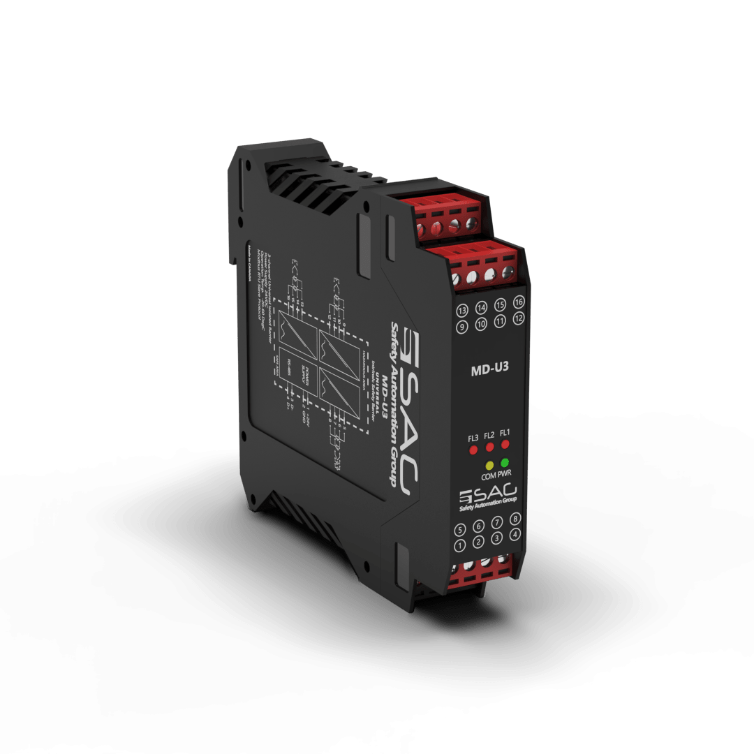
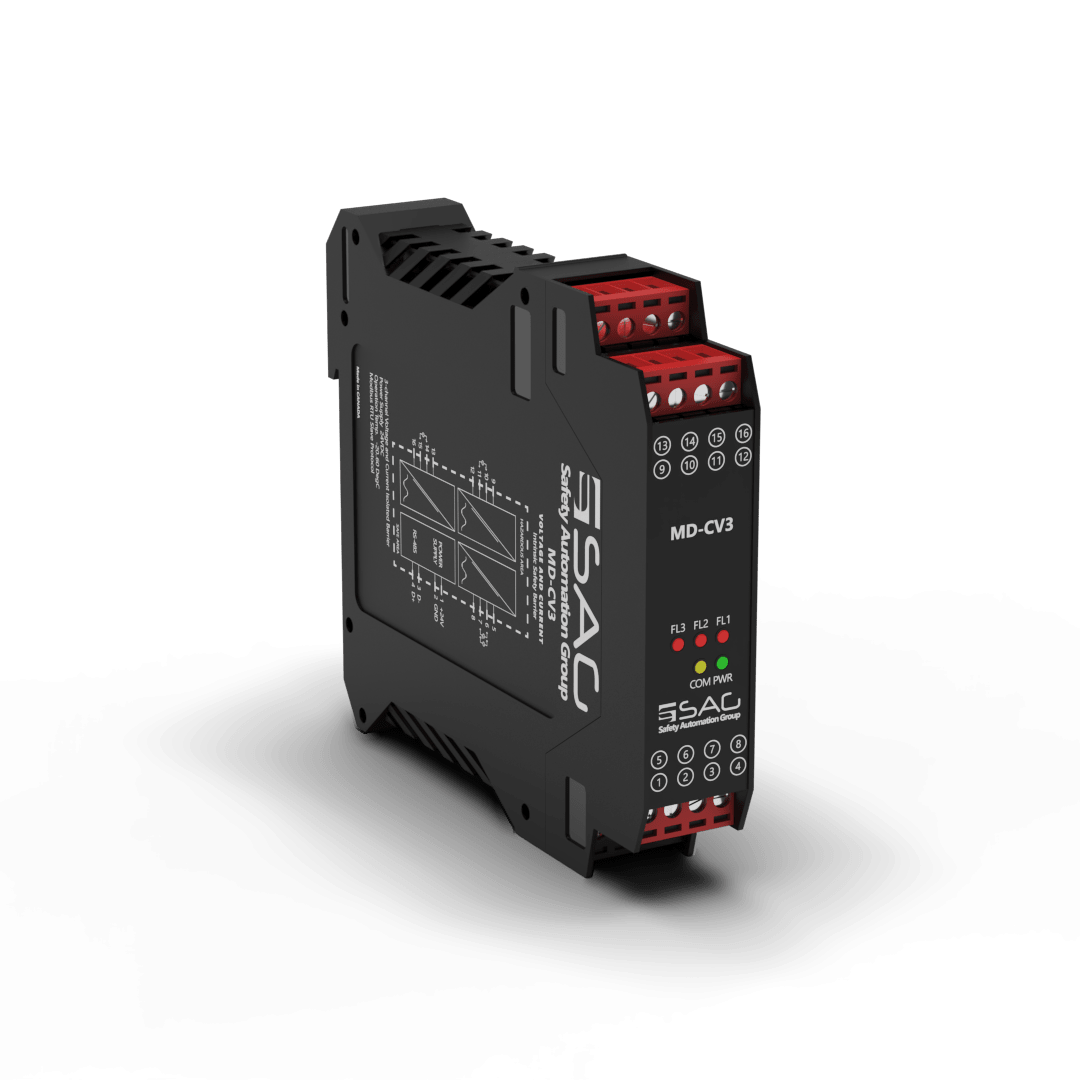
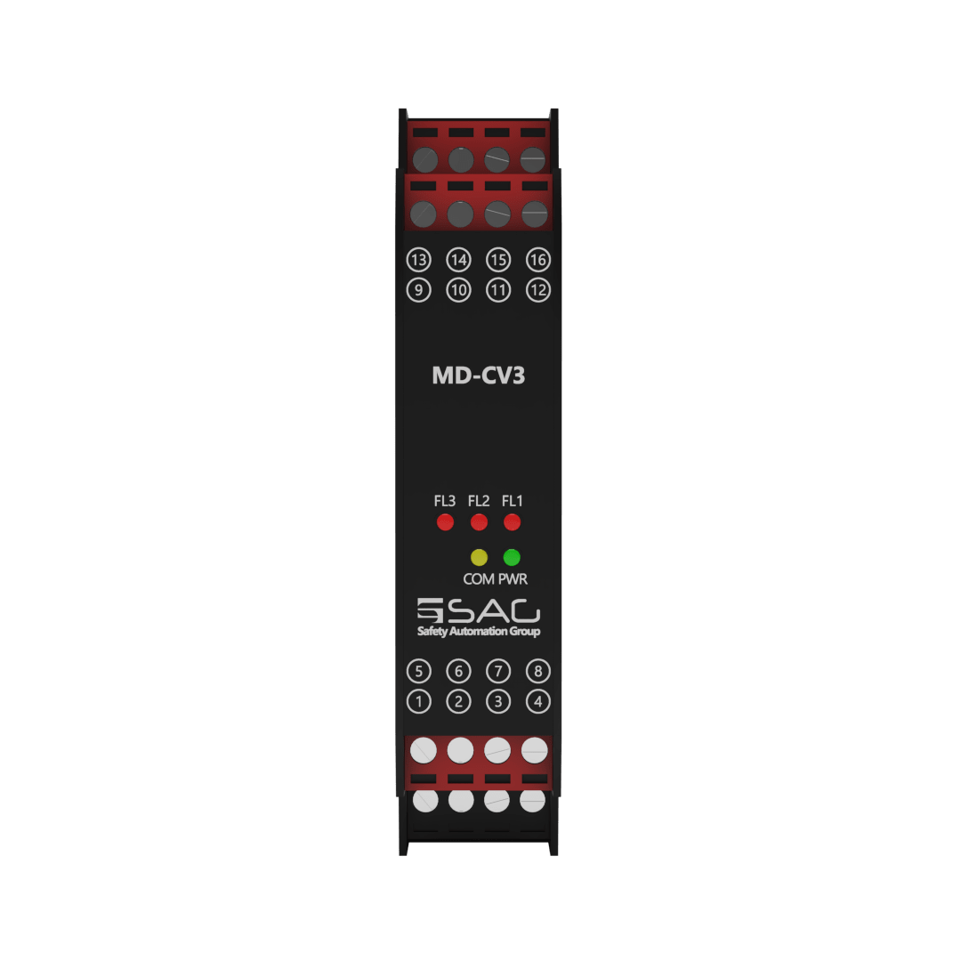
MD-CV3
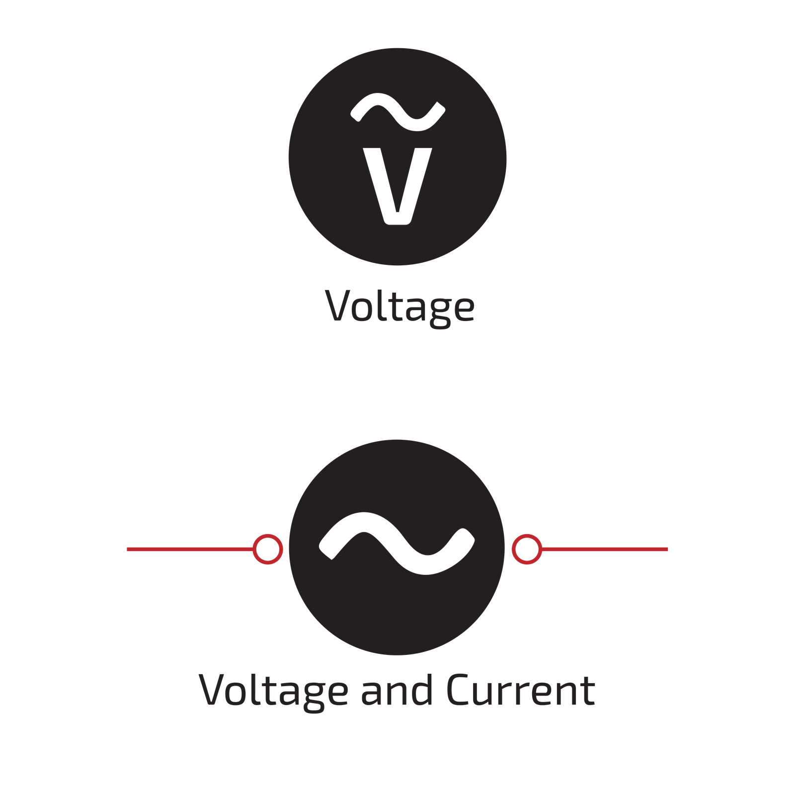
Current and Voltage Sink Analog Intrinsic Safety Barrier (3-Channel)
The MD-CV3 is a sink voltage intrinsic safe barrier. It can read analog signals from hazardous areas (Zone 0 or 1) and transmit their values to a safe area (zone 2) through MODBUS. The MD-CV3 can support three channels, and they can all make a connection with the main station and communicate through the MODBUS-RTU protocol on the RS485 serial port, with a baud rate of up to 115.2 kbps. This allows for simultaneous Monitor/Configuration on an integrated CPU when communicating with PLCs or PACs directly.
By using this barrier, you can preserve any equipment that becomes an ignition source, when they are in the vicinity of explosive gases. This is achieved by limiting the electrical and thermal energies. Furthermore, possible faults, which might occur due to short circuits and open circuits, will activate the Fault LED on the barrier to warn the user of possible danger.
MD-CV3 can measure analog signals like voltage and current (as it applies to one channel) in a wide range of voltages, from -5~5v, 0~5v, 0~10v, and -10~10v, through to current in the range of 0 to 20 mA and 4-20mA. The current and power consumption of the input is about 208 mA and 5W, respectively, and it is mounted on a 35 mm DIN mounting rail acc.
Product Features
- Support 3 Channels
- 24 VDC Supply
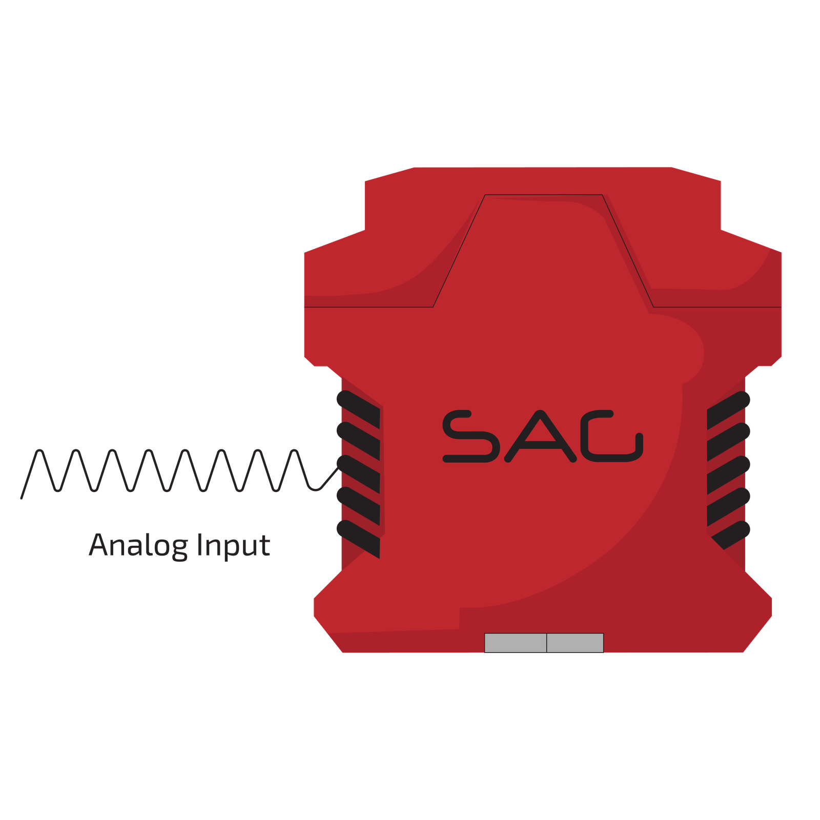
- Analog Signal Type
- Modbus RTU
- RS-485 Interface
- Connection with Screw Terminals
- Configurable with Modbus Protocol
- Voltage and Current Input


Technical Specifications
| GENERAL SPECIFICATION | |
| Signal Type | Analog Input |
| Number of Channels | 3 Channel |
| SUPPLY | |
| Rated Voltage | 24 VDC Nom (20-30 VDC) Reverse Polarity Protected |
| Connection | Terminal 1 PIN 1(+24 VDC), Terminal 1 PIN 2 (GND) |
| Power Dissipation | < 1 W |
| Current Consumption | Approx. 208mA |
| Max. Power Consumption | 5 W |
| INPUT | |
| Input | Current and Voltage |
| Connection | Terminals 2,3,4 |
| Rated Values | - |
| Integration Time | 400 ms |
| Input Range | (sink 0-20mA), (sink, -10 to 10 volts) |
| VOLTAGE | |
| Range | 0 ... 10 V, 2 ... 10 V, 0 ... 1 V, -100 ... 100 mV, -10 … 10V |
| Resolution | - |
| CURRENT | |
| Range | 0 … 20mA, 4 … 20 mA |
| Resolution | - |
| DEVIATION | |
| Voltage | 0.1 % of Span |
| Current | 0.02% |
| DATA CONNECTION | |
| Modbus RTU | RS-485 connection up to 115.2 kbps for Monitor/ Configuration |
| Connection | Terminal1 PIN 3 (D-), Terminal1 PIN 4 (D+) |
| ISOLATION | |
| Input / Power Supply | 1500 VDC Example. safe electrical isolation by reinforced insulation according to IEC/EN 61010^-1 Rated insulation voltage 300 Veff test voltage 3 kV, 50 Hz, 1 min. |
| ENVIRONMENTAL CONDITIONS | |
| Operation Temperature | Temperature Limits –20 to +60 °C |
| Storage Temperature | Temperature Limits –25 to +65 °C |
| MOUNTING | |
| Mounting | On 35 mm DIN Mounting Rail Acc. to EN 60715:2001 |
| APPROVALS | |
| IEC60079-0, IEC60079-11, IEC60079-15 | |
| FM & FM-C No.3024643,3029921C,conforms to Class 3600,3610,3611,3810 | |
| LOCATION | |
| Safe Area/Non-Hazardous Locations or Zone 2, Group IIC T4, Class I, Division 2, Groups A, B, C, D Temperature Code T4 and Class I, Zone 2, Group IIC, IIB, IIA T4 installation | |
| SAFETY DESCRIPTION | |
| ATEX | II 1 G Ex ic [ia Ga] IIC T4 Gc, II 3 G Ex ic [ic] IIC T4 Gc, II 1 D Ex ic [ia IIIC Da] IIC Gc II 3 D Ex ic [ic IIIC Dc] IIC Gc |
| IECEx | Ex ic [ia Ga] IIC T4 Gc, Ex ic [ic] IIC T4 Gc, Ex ic [ia IIIC Da] IIC Gc, Ex ic [ic IIIC Dc] IIC Gc |
| FM | Class 1, Zone 2 AEx ic [ia Ga] IIC T4 Gc, Class I, Zone 2 AEx [ic] IIC T4 Gc Zone 20 Ex ic [ia IIIC Da] IIC Gc, Zone 2 Ex ic [ic IIIC Dc] IIC Gc |
| North American Zones | Class I, Division 2, Groups A, B, C, D T4, Class II, Division 2, Groups F, G |
| ASSOCIATED ELECTRICAL APPARATUS | |
| Vo/Voc | 17.0 V, Io/Isc = 85 mA, Po/Po = 1.45 W |
| IECEx | 24V, Ci = 6 nF, Li = 0 nH. Um = 30 V, -20 °C ≤ Ta ≤ 60°C. |
Support & Download